LaiLA Concept - The Ultimate Laverda Triple classic racer - |
|
|

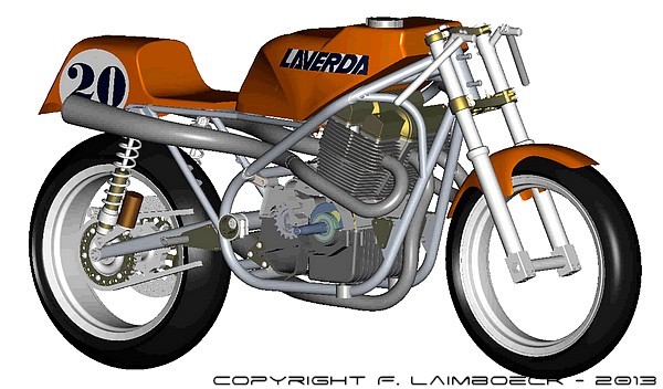
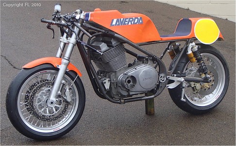
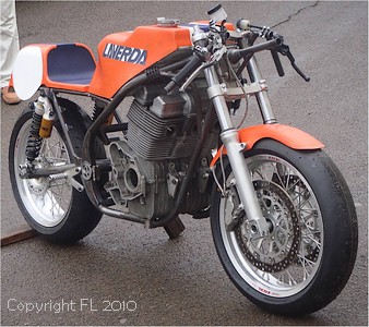
| October 2010; First try for the chassis and the bodywork (minus the full fairing). All goes to the right place! The bike has already a very racey attitude... |
|
|
 |
|
||||||||||||||||||||||
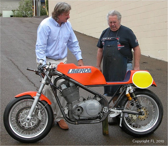
Franz laimboeck and Rob North: Two genius contemplating their creation... |
||||||||||||||||||||||
 |
||||||||||||||||||||||
With the special 3 into 3 exhausts |
||||||||||||||||||||||
UPDATE!! July 2011 |
||||||||||||||||||||||
 |
||||||||||||||||||||||
 |
||||||||||||||||||||||
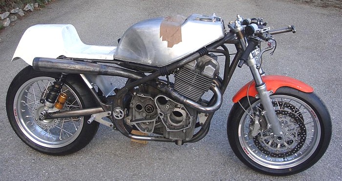
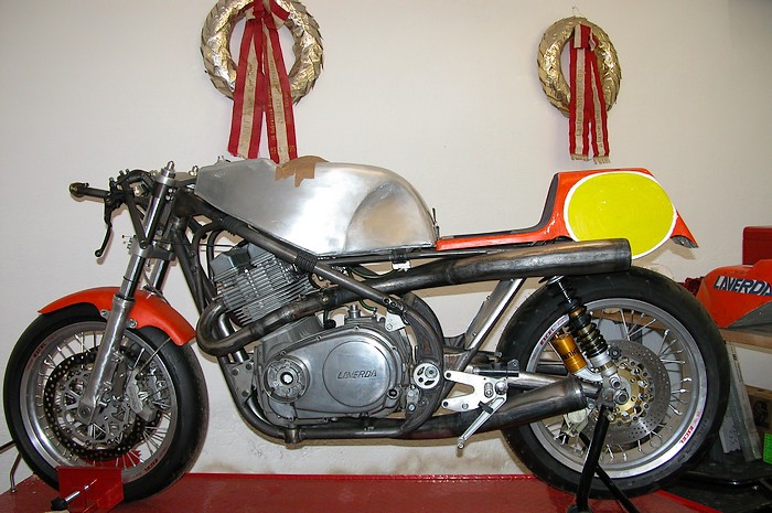
Note the offset sprocket |
||||||||||||||||||||||
 |
||||||||||||||||||||||
 |
 |
|||||||||||||||||||||
|---|---|---|---|---|---|---|---|---|---|---|---|---|---|---|---|---|---|---|---|---|---|---|
|
|
|||||||||||||||||||||
________________________________________________________________________
The work on the engine has finally begun. The least I can say is that it is as huge as the amount of work that had been already done on the chassis! Some technical information have to be kept secret of course due to copyright issues and as this is a race bike, so here what we can say at this stage: Franz plans 2 sorts of engine:
The 2nd engine (B88) will be totally new, all the casting, shapes, external and internal parts will be CNC built from zero with the most modern materials and technology. Part sizes and power will be even better than the 1rst project. All the skills that Franz is able to will be put into this project. A totally new cylinder head, higher that the original, will be designed and built. __________________________________________________________________________
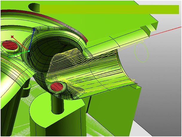
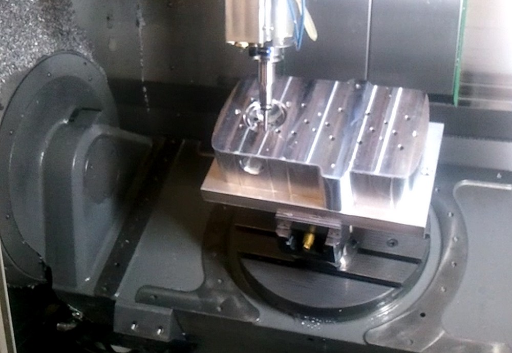
Last weeks have been used to program the software to CNC machine the combustion chambers and the ports. The number of hours spent to design the new cylinder head is beyond all one can imagine. The machine shown on the picture is one of the rare 5 axis CNC machine. No need to say that common human brains cannot imagine the cost of such a tool + the special software!! Here a picture of the initial program:
And here a picture taken from a video showing the 5 axis CNC machine working on the new billet cylinder head:
__________________________________________________________________________
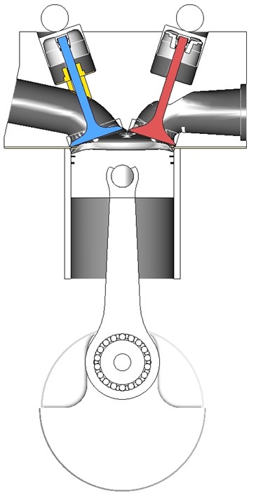
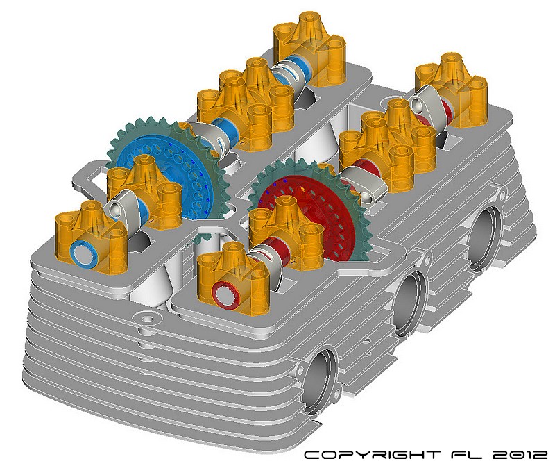
While the first dummy of the cylinder head has been done using the 5 axis CNC machine, work went on by studying the valve train, cams and pistons. This resulted in this developement for the cams and valves (click on the pictures to enlarge): New cam profiles are used, lobes are lightened and their lubrication is improved. Not less than 5 cam bearings are used for each camshaft.
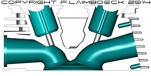
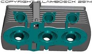
General shape of the new ports, combuston chamber and cams:
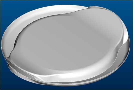
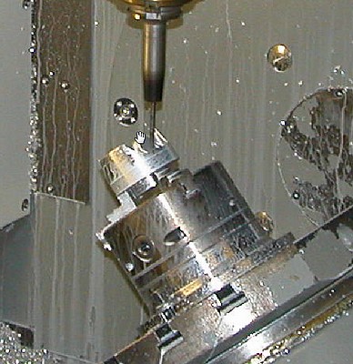
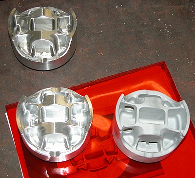
Another work concerned the pistons. Using the same 5 axis CNC tool, a very special, lightweight piston has been machined. Goal is a total weight of less than 180 grams per piston. Pistons will receive special piston rings (2), Nikasil coating and a very low friction factor:
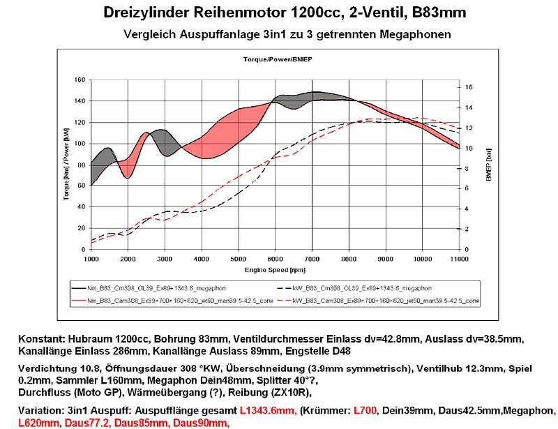
12 pistons and 50 rings have been manufactured in automn. The piston pins are in process of being DLC PVD coated with a new low friction MoNitrate and polishing which features a dry friction coefficient of 0,05 The cylinders are ready getting machined. The 3 copper head gaskets are ready. The connecting rods are offered from outside but the order needs to wait until the final cylinder heightis known after machining to adjust the conrod length accordingly. The welding of the first cylinderhead is in process but will require a total of 10 hours welding time to close the ports, combustion chambers, cup type tappets liners and valve guide holes and prepare the fixing locations for the 12 cam bearing caps. Needless to say that this is a critical path in the project as the weld can be porous (need to start over again) or the Tungsten Welding Electrode can break off and drop into the molten part of the weld leading to cutter damage when machining.... An alternative would be a new molding for cylinderheads, this is what we have in mind at this moment. Casting (Mahle 124 piston alloy T6 Heat Treatment) and machining would be in house. This sounds tempting as all weaknesses of the cylinderhead could be eliminated - still keeping the outside historic looks. On top of it, space and wall thickness could be provided also for the B88 (B90?) version with relocated stud bolts, maybe with a new cylinder casting too. Also the lower camshaft bearing caps could be integrated into the casting and oil passages can be improved. We have also in mind to try to cast-in the valve seat rings to avoid any loosening due to expansion and distortion. The 1D Thermodynamic simulation was done to optimize the cam timing along with the exhaust shape and it proved that 3 separate megaphones are superior above 6000 rpm until 8500 with excellent max. power but feature a nasty bulge in the torque curve at 5000 rpm with a torque gradient that will make it difficult to ride under slippery conditions. The 3in1 exhaust features a steady smooth torque rise with very acceptable power at 10000rpm. Hard to tell what will give faster lap times. On a fast circuit the 3 megaphones would have the edge but what about a slippery hairpin in the wet........ It should also be mentioned that the 3 megaphones (in the graph) are the ones that were done in the US and manufactured by hydroforming - now on the bike. The 3 into 1 was very carefully optimized with dozen of variants so it can be stated that the full potential of the megaphones is not been exploited yet.... Here is a comparison of both Power/Torque curves for the B83 engine:
In the meantime the design and simulation work has moved forward: Some videos are available on Youtube Video 1: Simulation of the 180° engine Video 2: Engine with the 3 into 3 exhausts Video 3: Another simulation of the 180° engine Engine data: 1200cc Bore 82.96mm, Stroke 74.0mm, Rated Speed 9700rpm, Compression Ratio 10.8:1, Twin Spark, Ports & Combustion Chamber 5Axis simultaneous CNC Machining, Intake Valve D45.0mm, Exhaust Valve D39.0mm, Valve Lift 12.4mm, AVL-Schrick Valve Springs, Exhaust Opening Duration 308degCA, Intake Opening Duration 308degCA, Valve Overlap Opening 4.5mm each, 6 Camshaft Bearings each, Vernier Cam Sprockets, PHM 38mm RoundBore Carburetors, ELKO-Mahle-Koenig Nikasil Bore - Torque Honing, Fine Honing, 2 Piston Rings, Piston mass 190g, Piston Pin OD18.0mm, Conrod Length 150.0mm, Ceramic Needle Bigend Bearing, PEEK cage 36x46x22.7 Original LAVERDA Castings Cylinderhead, Cylinder, Crankcase CAD on PTC ProE WF4, 1D Thd on GTPower
Last details of the new cylinderhead design, 2 valves per cylinder version:
Engine and its new cylinder head into the frame:
New simulation available here: Video
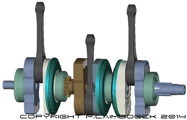
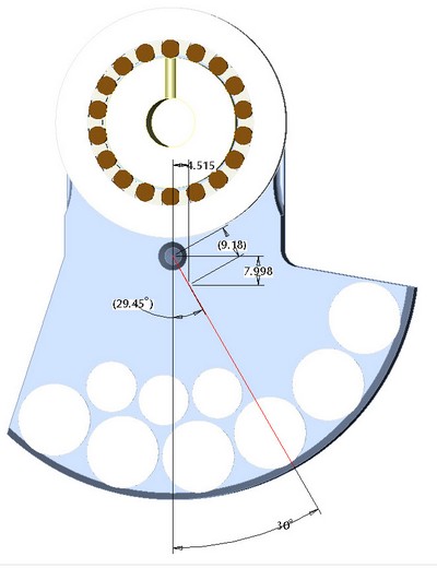
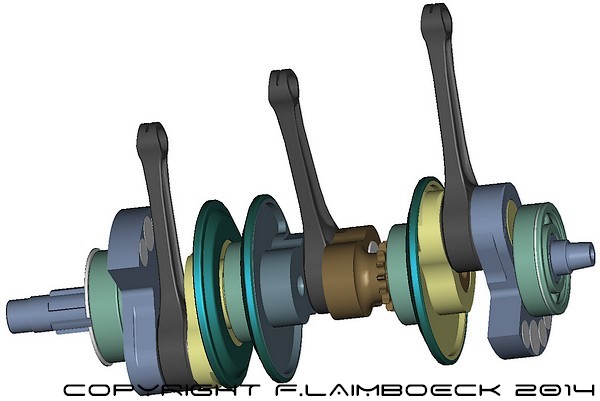
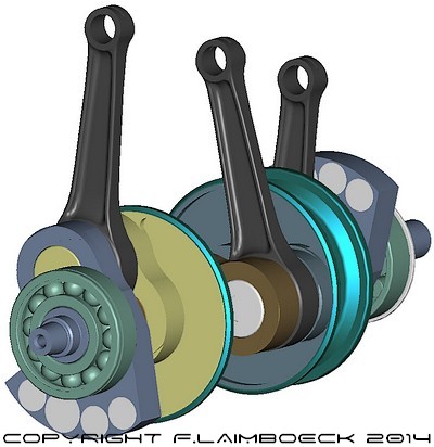
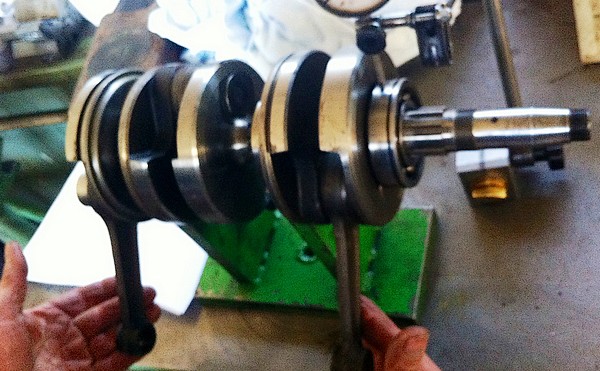
Work on the crankshaft: Here is the latest design of a 180° Crankshaft for the LaiLA B83 1200cc project. It came out that the total weight of the crankshaft is now 12.100g (compared to the 17.300 g production 180°). It features new L150 connecting rods with D18 piston pin, new bigend bearings with 5X machined Aluminum cage hard-anodized, and numerous heavy -metal Tungsten-Carbide (density 15,6) plugs to arrive at the ideal balance factors at light weight. The balance factors of cylinder #1 and cylinder #3 are 33% and the factor for the central cylinder #2 is set to 10% which - along with the oscillating masses reduced to almost half - results in lowest possible vibration (according to simulation).
And here is the work on a 240° crankshaft - aiming at most light weight - , it is possible to arrive at a 50% balancefactor of the free 1st order Inertia Moments by simply adding balancemasses only to the outmost crankwebs #1 and #6 which are balancing the free 1st order moments by 50% but also 100% of the rotating masses - as the other 4 crankwebs (2,3,4,5) are left without any balanceweights.
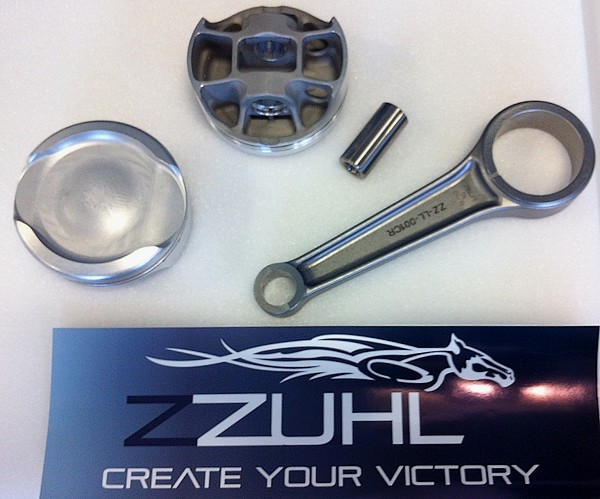
ZZUHL Connecting Rods along with the MoN coating of the ZZUHL Piston Pins (Nitrided Steel with quarter ellipse inner end shape) just arrived! (ZZUHL website: http://www.zzuhl.com/)
The work is going on for both 180 and 240 degr. crankshafts. It came out that the total weight of the 180 crankshaft is now 12.100g (compared to the 17.300 g production 180°). It features new L150 connecting rods with D18 piston pin, new bigendbearings with 5X machined Aluminum cage hard-anodized, and numerous heavy -metal Tungsten-Carbide (density 15,6) plugs to arrive at the ideal balancefactors at light weight. The balancefactors of cylinder #1 and cylinder #3 are 33% and the factor for the central cylinder #2 is set to 10% which - along with the oscillating masses reduced to almost half - results in lowest possible vibration (according to simulation).
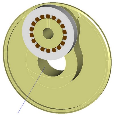
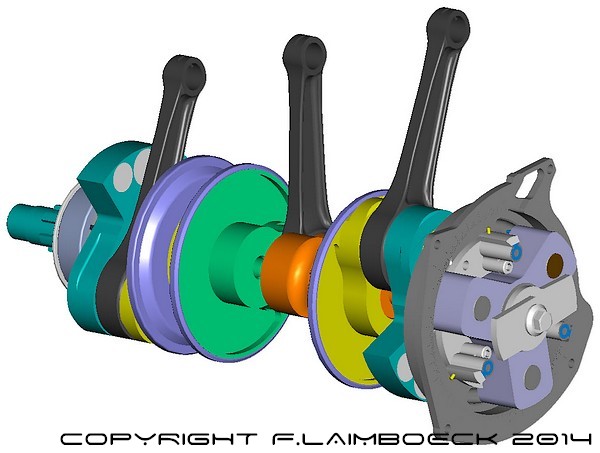
Presently the work on a 240° crankshaft - aiming at most light weight - is in process and it seems possible to arrive at a 50% balancefactor of the free 1st order Inertia Moments by simply adding balancemasses only to the outmost crankwebs #1 and #6 which are balancing the free 1st order moments by 50% but also 100% of the rotating masses - as the other 4 crankwebs (2,3,4,5) are left without any balanceweights. It should be mentioned that the crankwebs of both crankshafts the 180° and the 240° are derived and made from existing 180° crankshafts parts. Picture below shows the later design with a Kröber ignition.
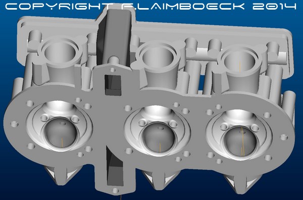
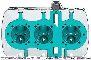
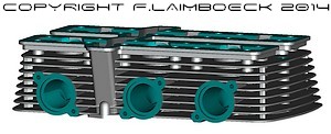
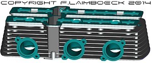
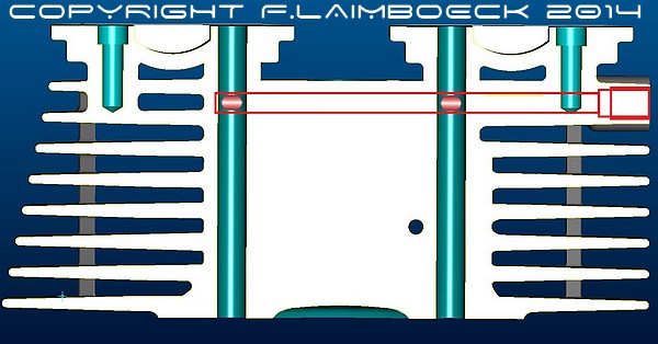
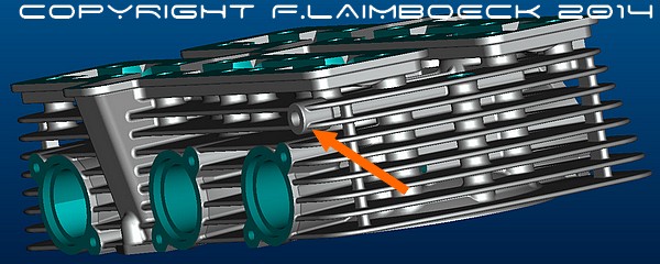
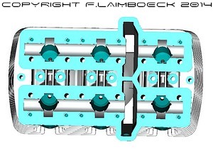
Here an update of the accomplished CAD Design of the Testa B83 with LaiLA Porting. The screenshot areas highlitghted in turquoise are the later 5X machining areas.
Another important point is an improved oiling system : A 6mm drilled hole crosses the far left 10mm stud bolt holes and uses these furtheron for lubrication.
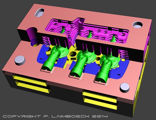
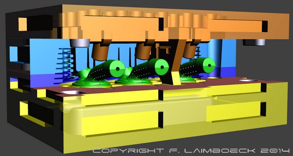
In order to build a entirely new cylinder head, we have done the first layout of the SandSinterForm (3D Sand Printer) molds for the LaiLA B83 Testa Cylinderhead. The mold design still requires some refinement to ensure the lowest possible porousity. Some cooling iron inserts in the valve seat and spark plug area will help. A possible cast might be in "N" alloy AlSi8Cu3NiMg and T7 heat treatment with cold air quenching to arrive at a 120HB Hardness in the stressed areas.
Stay in touch for new updates soon! Click on 'next' for the technical data |
||||||||||||||||||||||
| <<< Back | ||||||||||||||||||||||